Using an Arduino to phase control 220V AC mains power.
Warning!
Mains electricity can kill you. If you don't know what you are doing, don't do it. You have been warned.
Why do it?
Now that I generate my own solar power, I wanted to be able to make the most efficient use of it. In the UK the Feed-in-tariff system means that you get paid to generate electricity, even if you use it yourself. Some appliances, eg. a kettle, will use a lot of power. This will only be free power if you are generating more solar power than the kettle uses. It makes sense to have a lower power kettle, boil it slightly slower, so that you only use solar power. Otherwise you will have to top up the power by importing it, which costs money.
I realised that if I could reduce the energy used to power the kettle, up to the available solar excess, I could often boil the kettle for free. An even better idea is to power an immersion heater to pre-heat your water. This will reduce the cost of heating your water, using free solar power. Actually it is more efficient to use a solar water heater, and cut out the electric bit entirely, but I don't have one of those, and my whole available roof space is already devoted to PV panels.
Triac control. Does it help?
The traditional way of proportionally controlling mains electricity is by using a triac. These 3-terminal devices can be triggered to act as an on-off mains switch. Once they are turned on, they stay on until the voltage across them is reversed. This will happen every half of an AC cycle. To accurately control the power you need to know where you are in the mains cycle, so you can turn the triac on in the appropriate place.
One problem with this approach is that although the average power applied to the load is less than the usual total, when the triac is 'on', the current it draws is the same as the full-load case. This could render the whole project futile. The consumption meter should alternate between import and export. When the triac is off, you don't use any power, free or otherwise. When the triac is on, the current drawn will be the same as when driving a load fully, ie. maximum. This instantaneous current will exceed the energy being produced by the solar panels. The question was, does this make the meter go round? It depends how the meter sums the power over time.
Time for an experiment. I expected the experiment to fail, but I am curious.
Zero crossing detector
I needed a way of detecting the zero crossing point of the mains cycle. One way of doing this is to use a special AC opto transistor. This can be placed directly across the AC mains supply, in series with a resistor to reduce the peak current. Unfortunately, the power dissipated by the resistor goes up with the square of the voltage. At 120 V AC you can get away with it, but at 220 V AC the resistor is likely to waste 3 or more Watts.
So, I decided to use a transformer to reduce the AC voltage down to a more reasonable level. The transformer can also generate a power supply for the rest of the electronics. The transformer I've used is a centre tapped 6V-0-6V type. I used this because I had one spare. It is not the best choice. If you are looking for a high efficiency power supply, look the other way. This isn't it. It is a simple circuit, but I'll describe the calculations I used to pick the component values, as it might help other people to see the process. Better still, buy yourself a copy of The Art of Electronics, by Horrowitz And Hill. A great book, but can we have a more up to date edition please?
The zero crossing detector is an opto device with 2 back to back LEDs, driving a single photo transistor, the H11AA1M. This works very well. Connected across the outer windings of the transformer, (6 + 6) * √2 = 17V peak across the transformer output. Subtract the forward voltage across the LED, 2.4V, gives 14.6V peak across the resistor. For a drive current of 10mA, V=IR, R=V/I, R = 14.6/10mA = 1.5kΩ So I put in a 1kΩ, which gives us a peak current of 15mA. A quick check on the power, P=IV, P = 15mA * 14.6 = 0.22W peak, /√2 for 0.15W average, so safe dissipation.
The Triac driver circuit
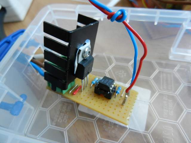
We want to electrically isolate all those high, dangerous voltages from the rest of the circuit. So, use an opto isolated triac, in this case the MOC3020. This switches on a higher current rating triac, the BTA25-600CW. This is a 25A device. More than capable of switching on a kettle. It has an insulated tab, so you can mount it to a chassis heatsink without risk of electrocuting yourself.
The triac drive circuit is simple. It only works with resistive loads. If you want to drive an inductive load, you will need snubber circuits on perhaps both of the triacs, and more complex drive signals. And, I confess, I copied this circuit out of an application note. It said the gate resistor should be 180Ω, but I didn't have any, so I put 2 100Ω resistors in series instead. Which isn't far off.
The LED resistor was chosen by: min current for turn on (from datasheet) 10mA, 5V drive voltage, forward voltage across the LED is 1.5V (from datasheet), so 3.5V across the resistor. 3.5/10mA = 350Ω max. 220Ω gives us 16mA, a safe margin.
Arduino Controller
The rest of the functionality of the system is provided by an Arduino. This, powered by the unregulated 9V input from the PSU board, takes an interrupt signal from the zero crossing detector, and sends control pulses to the opto-triac.
The zero-detect signal is taken to pin 2 of the Arduino, an interrupt input. This is configured to generate an interrupt on CHANGE. This will occur at the start and end of the zero-crossing detector pulse. It is safe to connect the analog output of the detector to the digital input because it incorporates a Schmitt trigger, which prevents multiple interrupts on slow or noisy edges. The zero-crossing detector's transistor is powered by pin 3. You could just hard wire it to 5V, but I decided to enable control of the transistor in software.
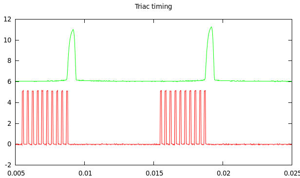
In this 'scope trace you can see the zero-crossing interrupt (green), which produces a pulse every 10ms, and the train of triac pulses, delayed from the zero-crossing pulse by the selected phase. The voltage of the green trace has been shifted up 6V to make the graph easier to see.
Timer1 is used to generate all the required timing via a state machine. The possible states are ZERO, PHASE, PWMHI, PWMLO. On the start of the zero-crossing period, which occurs just before the physical zero crossing of the mains cycle, you get an interrupt. By reading the state of the port you can determine whether it is a start or end of the pulse. At the start of the pulse we enter ZERO state. This will clear any output signals, ensuring that the drive to the triac is off before the mains voltage goes negative.
When the end of zero-crossing interrupt occurs, we know we are on the start of the next mains cycle. We now enter PHASE state. This starts a delay using Timer1. The delay is dependant on the desired phase at which we want to turn on the triac. When the timer expires, we enter PWMHI state. The triac is switched on for a short period, again, timed using Timer1. When the timer expires we enter PWMLO state. This switches off the triac drive. But the triac is now in conducting state so will stay on until the next mains voltage reversal. I chose to repeatedly pulse the triac, so PWMLO goes back into PWMHI until the sequence is stopped by the arrival of the next zero-crossing interrupt.
The Timer is clocked by the 16MHz processor clock, divided by a prescalar of 8. So we have a 2MHz clock, ie. 0.5µs per timer count. The mains half-cycle at 50Hz is 10ms, so we have 20000 timer counts per half-cycle. I decided to use µs as the units in the code, so the macro COUNTS(x) simply multiplies the µs count by 2 to give the timer count.
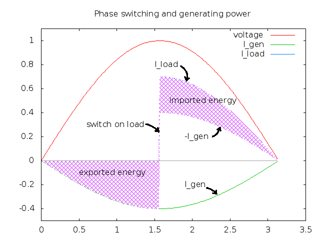
The voltage available across the load will be a sine function. For a resistive load, the power (P=IV) will be a sine2 function. The power distribution across the half-cycle can therefore be calculated. We need to integrate the sine2 function. My maths is rubbish so I looked this up here.
sin2(x).dx = (0.5 * x) - (0.25 * sin(2x))
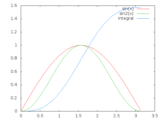
The above graph shows the sine, sine squared and the integral for a half cycle. The green curve shows how the instantaneous power varies across the cycle. The integral makes sense drawn like this. The (0.5 * x) part is simply a straight line from 0 to π/2. You can see how the (0.25 * sin(2x)) is subtracted from this, causing the ripple in the curve. The sine2 curve is symmetrical, so the midpoint of the integral must lie on the (0.5 * x) line.
Digression: interestingly, the sine2 function is very similar to the power output of solar panels. As the sun moves laterally (azimuth) across the sky, the angle the panel makes with it is a cosine function. As the sun moves up and down vertically (attitude), it traces out part of another cosine function. The amount of sunlight falling on the panel is thus a cosine2 function, purely as a result of the geometry of the panel relative to the position of the sun.
I wrote a simple Python script to calculate a set of 100 bins, which divide the power distribution across the mains cycle into roughly equal amounts. This is used to generate the table powerlut50Hz. This converts from percent power to the number of µs needed to wait before switching on the triac. If you wanted to run this at 60Hz, you could either hard code a different table, or you could measure the frequency by comparing the time between successive zero-crossing interrupts. This could then be used to select between 2 tables. In this way you could automatically adjust for different mains frequencies.
The power look up table needs to be offset slightly, as the PHASE mode starts later than the actual zero crossing. I can estimate this time by taking the midpoint between the 2 edges of the zero-crossing pulse. I need to subtract this number as the "already done this" phase. This is not exact, but the error is not large. You can see from the triac timing graph that the zero-crossing waveform is not symmetrical. I think this is due to the uneven load on the transformer caused by the power being taken by the Arduino. If you have a mains-fed opto detector you won't have this load and the waveform should be symmetrical.
The table assumes a perfect sine function, but it is a reasonable approximation. So, we can now request a percentage power, and the triac will be switched on at the right time to apply that power to the load.
Bluetooth Communication
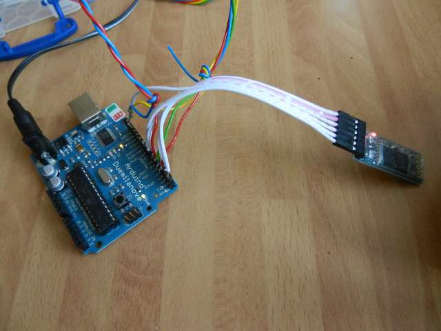
I wanted to be able to communicate with the device remotely, so chose Bluetooth as an off the shelf protocol. I bought some cheap Bluetooth modules on e-bay. These are easy to interface, having built in 5v to 3.3V level converters. It acts as a serial interface. You can directly connect them to the Arduino's Rx & Tx pins. If you use a port output to power the module, it can be turned on under software control. This gives the added bonus of disconnecting the bluetooth module when the board is reset. This allows you to use the FTDI interface at the same time, so you can upload code to the board with the bluetooth module connected, sharing the Rx & Tx lines, without the serial data being corrupted.
I can now control the triac phase using my Android phone. There is a useful app called BlueTerm that allows you to connect to a bluetooth serial device, and send and receive data. The command protocol I came up with is simple. "sxx\n" where "xx" is the percent power required.
Putting all the bits together, I can now control the power applied to a load using my phone. I didn't bother with a fancy app for the phone. That can come later. I tested it with an incandescent lamp. It obviously won't work with a low energy fluorescent lamp.
The Kettle Test
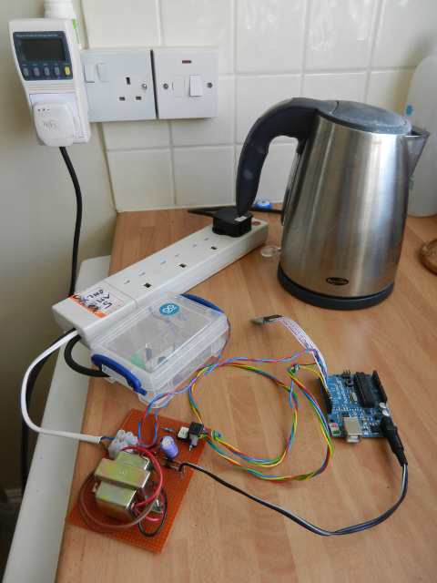
We now have everything in place to perform the test. I chose a time when the solar panels were generating less than the rating of my kettle. The kettle is a fairly low powered one, 1800W. The panels were generating 960W one evening. I set the power output at 40% using the command "s40" on my phone. When I switched the kettle on, the power meter read 834W. I had little else switched on in the house, a couple of low powered servers, router, WiFi access point, all less than 80W total.
Looking at the import electricity meter, it didn't move. It is one of the old variety with a spinning Aluminium disk. The kettle boiled, slower than usual. The triac got hot (I still haven't got adequate heat sinking on it). A success!
Conclusion
I didn't think the experiment would work, as obviously the 'on' period peak current exceeds the instantaneous current provided by the solar array. The conclusion must be that a) the import meter is summing import and export power, b) the energy is being stored somewhere else, or c) I've missed something.
In the spinning aluminium disk meters, the disc acts as an integrator. This is where the energy is being summed. So, this only works if you have a meter that integrates over a long period of time, ie. at least a half mains cycle. If the meter only takes the instantaneous import current, multiplies by the voltage and integrates that, the experiment will fail, the meter will show a net import taking place.
Older meters weren't really designed to cope with exported power. They clearly have some form of "rectification" to prevent them from being driven backwards but this is presumably mechanical, perhaps a friction ratchet on the disk? They still sum the positive and negative currents.
However, meters also have to cope with reactive power. If you have reactive loads, then the current and voltage are out of phase. The provider should not charge you for reactive power, so they should cope with current flowing back to the grid. This suggests that the design of meters must sum both positive and negative currents.
I need to repeat the experiment using a different import meter.
Future Development
I need to put an adequate heat sink on the triac, which gets too hot for normal use. It needs a safe box to put it all in! It also needs some filtering to prevent EM interference.
For a full system it needs to know the available excess power. This would need to be pushed to it over the bluetooth interface. It will also need a lower threshold at which it will always import power, otherwise you won't be able to boil the kettle at night. I would also add a set of push button switches and LEDs. I would have 3 buttons, 'off', 'eco' and 'full'. An LED on each switch would show the state - a slow changing green LED for eco mode, brightness proportional to the excess power available. An angry flashing red LED on the 'full' button to show any imported power used. The 'off' button can have an LED that also shows the bluetooth connection status.
I'd also like to look at a different power circuit. Instead of using a triac, I could rectify the mains, then chop it at HF using a FET or IGBT. This can drive a filter to remove the RF and store the energy between pulses. I can then drive the kettle with variable voltage DC, instead of chopped AC. This should work with any import meter.