Decoding the signal from a commercial reversing sonar
October 2011
I bought a reversing sonar to fit to the car. I thought I would open it up and have a look inside. I was surprised how old fashioned the design was. All those 0.1 inch parts. The board looks like this :
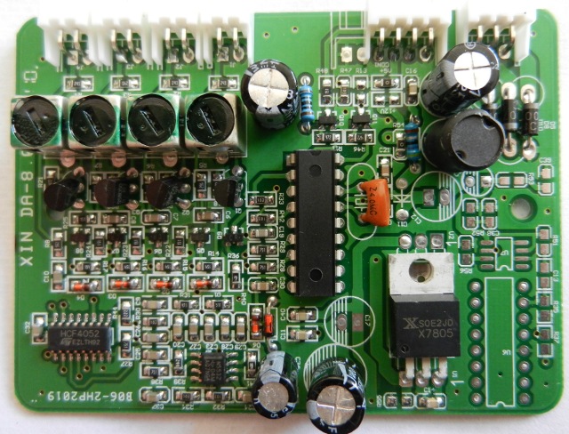
The device drives 4 transducers, connected to the 4 plugs at the top left. The power is 12V, on the 3 pin plug top right. The remaining 4 pin plug connects to the display unit mounted on the dash board, via a cable.
The processor appears to be a PIC16F84 or similar (it has the right pinout for power and clock) though it has had the numbers removed. By coincidence I designed a simple phased array sonar system using one of these chips a few years ago, so this caught my eye. There is a 7805 linear 5V regulator, the transistors near the ultrasonic drive are SS8050 NPN devices, 1W, 1.5A, so must be the power drive for the transducer.
There is an analog multiplexor 4052, ganged 1-of-4 selector with A, B, inhibit inputs (inhibit tied low). 4 outputs go to the base of the driver transistors, the other inputs come from the smaller surface mount devices, presumably input amp. And a dual low-noise op amp, NE5532, which must be the rx stage.
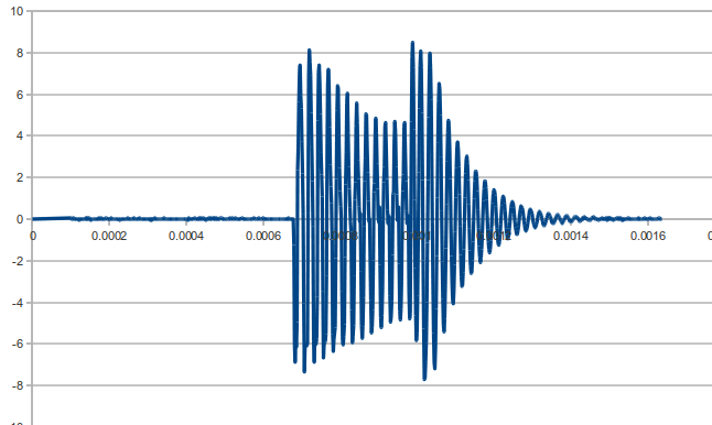
The tx pulse is driven with the NPN driver through a transformer, which seems to be driven with around 13 pulses of 40kHz. This produces a resonance in the transducer, seen here :
The drive to the display only has 3 wires, so it must be power (to drive all the LEDs), ground and signal. So had a look at that instead. There is another microcontroller on the back of the display board, which drives a 7-segment display showing 0.1 metre increments, some LED bars for left and right, and a very loud buzzer.
The signal looks something like this
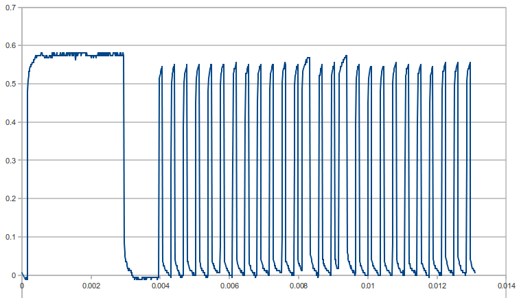
The initial hi/lo timing pulses are around 2.8ms and 1ms respectively. The remainder of the pulse train seems to have hi/lo transitions at regular periods, so the data must be encoded in the lo/hi transition point within the bit stream.
The period of the bits seems to be about 355µs from hi-lo to hi-lo, with the hi period being around 100µs for '0' and around 255µs for '1' (guessing the values here). So, roughly a mark-space period lo:hi 255:100 for '0' 100:255 for '1'.
There appear to be 33 bits in the sequence, so, if the first is a sync, we probably have something like 8 bits per sensor for the 4 sensors.
I connected the output up to an Arduino board. The 5V signals can be connected directly to it. I used pin 2 interrupt on the Arduino to detect changes in the line status
I wrote a decoder to recover the bit stream and discovered that it uses a simple encoding, as described above. The data for each sensor is output as binary N where :
distance = 2.5 - ((N - 1) * 0.1) metres
so, 1 -> 2.5m, 2 -> 2.4m etc down to 23 -> 0.3m (23 = 0x17). The encoded range is therefore 2.5m to 0.3m.
The start sync is 2.8ms hi, 1.0ms low, followed by a brief high pulse, followed by the data bits.
There are 32 bits, 8 for each sensor. Bits are transmitted in sequence hi .. lo, in order sensors B,A,C,D (as they are labelled on the case). The sensors are only reported in pairs on the LEDs, with the nearest signal showing as a 0.1 metre resolution step. I suppose that the nearest thing to you is the most important when reversing.
The next thing is to hook it up to my phone to display the sonar signals ...
Other tear-downs :