Remote Phase Controlled Power Source
Warning!
Mains electricity can kill you. If you don't know what you are doing, don't do it. You have been warned.
The System
What I wanted was a way to control the power to a load so that it only used 'excess' solar power, ie. power I'm generating but not using myself. You can make use of this power in an immersion heater, to provide hot water, or additional electric heating. I don't (yet) have an immersion heater, so I'm using a kettle as the load.
You need to monitor the import / export status of your electricity meter, and to be able to control the power to a load. If I was driving an immersion heater I wouldn't bother with a radio link as the import meter and the spur to the heater are typically right next to each other. To drive more remote loads, such as heaters and kettles, you need a communications link. I'm currently using my home made energy meter, because I have one already. A more suitable system would be something like the system produced by OpenEnergyMonitor. I would also use a different box for an immersion heater controller.
Having built my own energy monitoring system and investigated phase power control I had nearly all the parts in place for a remote controlled smart power switch. I also needed a good radio communication system, and preferably something smaller than the Arduino. I have been following the fascinating blog at JeeLabs for a while. The JeeNode with its RFM12B radio seemed like exactly what I was looking for. They are great little boards.
The Electronics
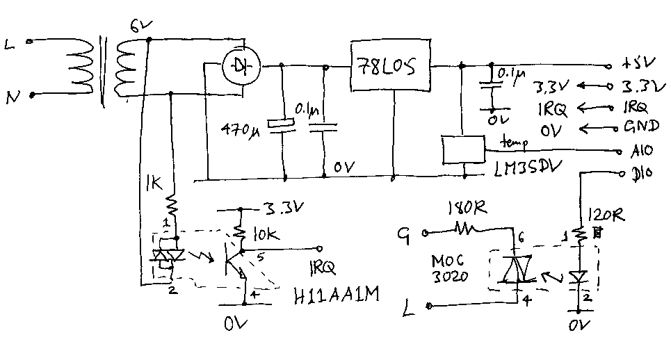
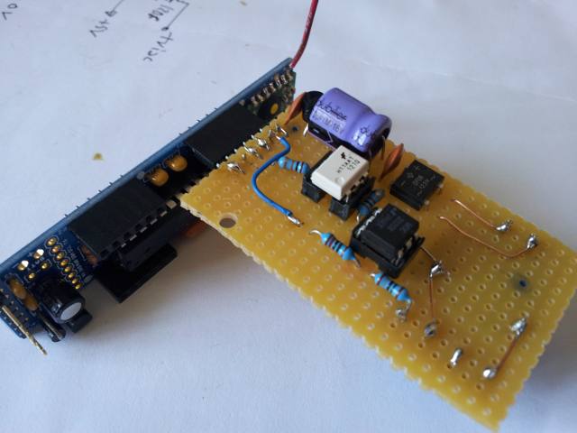
The circuit is based on my earlier work and is straightforward. It provides a 5V linear power supply (this is further regulated down to 3.3V on the JeeNode), a zero crossing detector connected to the interrupt line, and an opto-isolated triac. I also added an LM35DZ temperature sensor so I could monitor the temperature of the unit. It fits neatly onto a single 'port' of the JeeNode.
The JeeNode arrived promptly. It was easy to build and get up and running. I bought a few of these great little boards, a USB BUB interface for programming and development, and a spare RFM12B breakout board to allow me to use an Arduino for the tethered radio node.
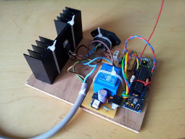
Here is the first prototype, with the components mounted to a block of wood. I used a large heatsink as I'm still not sure how hot the device will get. Perhaps someone can point me at a good website that explains how to choose a heatsink for a triac?
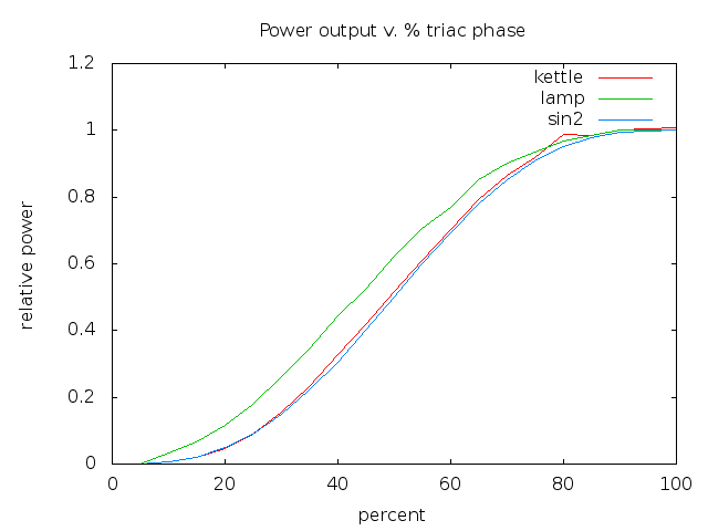
This gave me the chance to measure the power output at different phases, seen here plotted alongside the theoretical curve (explained here). The kettle follows the theoretical curve very closely. The 60W incandescent lamp does not. I think this is because the coil resistance is very low when cold, so you get higher than expected current at low phases, hence higher power consumption. It is this property that causes incandescent bulbs to sometimes blow when you switch them on because of the inrush current.
The Hardware
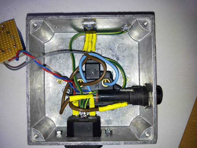
I needed to fit all this into a box. I wanted it to have a standard UK mains socket on the top, so chose a box just big enough for this. This made it a bit of a challenge to fit the electronics inside. I don't have the facilities for making something like this, but a friend let me use his workshop, and then ended up doing all the work too. Many thanks John. Great job.
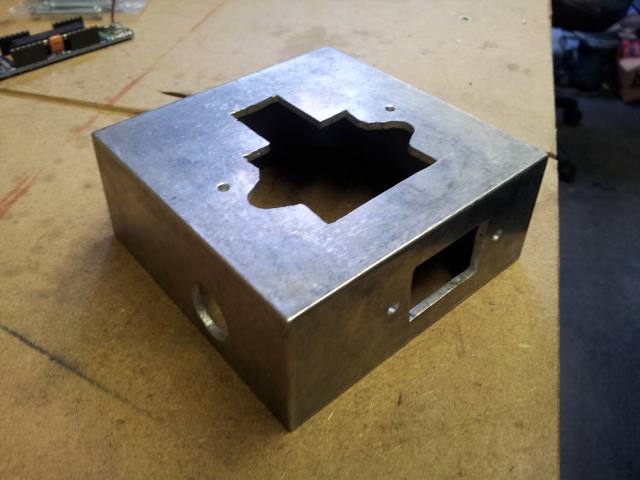
With the socket, IEC inlet, triac and fuse holder mounted, the inside of the box looked something like this. The power triac I'm using, the BTA25-600CW, has an insulated gate, so it is safe to mount it to the metal chassis. It is essential to earth the case too.
I'm still not sure how much of a heatsink I need. It was originally intended to mount a large finned heatsink on the outside of the box, but as the prototype never got remotely warm I decided to try with just the box as a heatsink for now.
To prevent any nuts falling off inside the case I've since glued them to the box, with the help of the Greek glue goddess, Araldite. That should help prevent any nasty accidents with loose nuts rattling round the inside of the box.
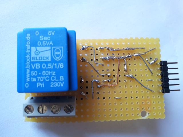
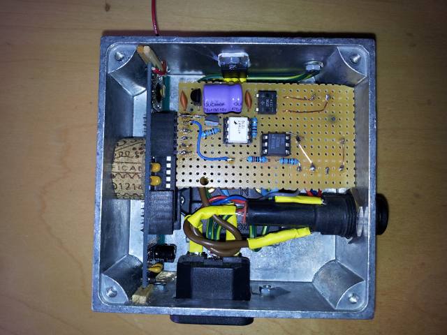
By mounting the JeeNode down one side of the case and the power interface board across the top of the earth pin, with the transformer mounted underneath, I managed to cram the boards into the available space. Here are the boards fitted together, and the underside of the power board. I also used a smaller transformer than the first prototype, to save space, the rs:732-0516.
I had some trouble mounting the JeeNode. I couldn't find any suitable card guides and the JeeNode has components mounted right up to the edge so is difficult to fit. The end result is a little unsatisfactory. For a second unit I will have to make a special mounting bracket. I'll have to buy a 3D printer for that I think :) But I found a strong compressible insulator, suitable for holding the boards in place - cork. Another two bits of cork were glued to the lid to hold the two boards firmly in place. I should emphasize here that the JeeNode is galvanically isolated from the mains voltage.
The most unsatisfactory part is the antenna. This is currently sticking out the side through a hole originally meant to hold a larger heat sink. I may try fitting it to the inside of the power outlet, wrapped around the edge. It won't work inside a metal box. I really need to be able to monitor signal strengths and I don't currently have the facilities. My one criticism of the RFM12B radio board / JeeNode combination would be that access to RSSI data is poor.
And here is the finished product. Not much larger than a standard UK mains pattress.
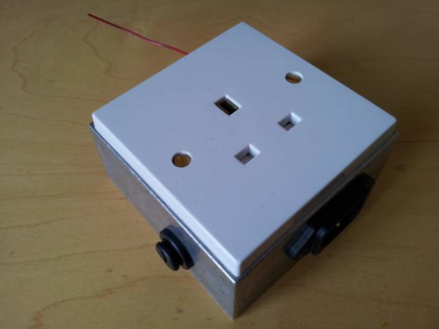
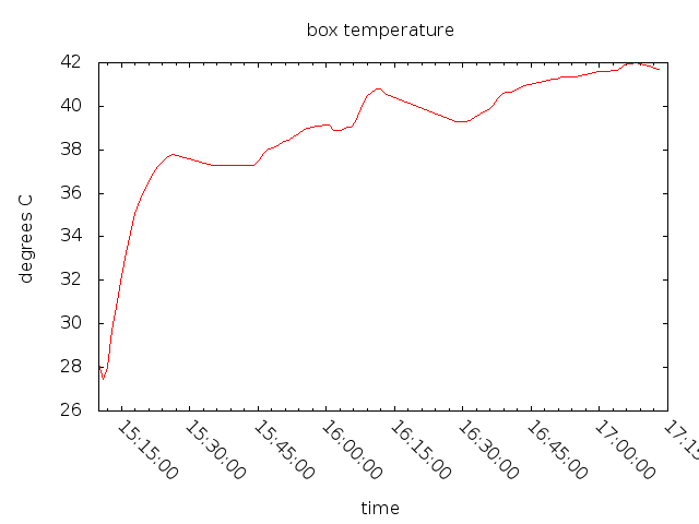
I can monitor the case temperature in software so I can keep an eye on it. I'm still not sure about the heatsink requirements. My temperature sensor data is pushed to cosm, so you can watch it too. From cold it typically looks like the graph below. This shows a rapid warming up to its operating temperature, caused by the heating of the transformer mainly. This rises when switching a load. I haven't run the load long enough yet to see at what temperature it levels off at. That will determine if the existing casing is adequate, or if I need some additional heat sinking. One of the joys of cosm is that you can set triggers to eg. send you an email if data goes above a pre-set level.
The Software
Having chosen a radio interface, I also needed some network infrastructure to get the two or more devices to talk to each other. I chose a star network architecture for now. I hope to develop a mesh system if I have the time at a later date. The triac controller board is in two parts, the triac controller and the radio interface. I've made the triac controller into a library so that can be reused in other projects.
Only one triac output is currently supported. Sharing the timer1 control between multiple triac outputs would be possible.
#include <triac.h>

// Specify the hardware pins and interrupt line
#define TRIAC_PIN 5
#define ZERO_CROSSING_PIN 3
#define ZERO_CROSSING_IRQ 1

// Provide functions to read the zero crossing state
// and write to the triac gate.

static void set_triac(bool on)
{
    // function to write to triac control hardware, e.g.
    digitalWrite(TRIAC_PIN, on);
}

static bool get_zero(void)
{
    // function to read zero crossing state, e.g.
    return digitalRead(ZERO_CROSSING_PIN);
}

// Create a Triac instance
static Triac triac(set_triac, get_zero);
Initialise the triac object in the setup() function.
void setup(void) {
  triac.init(ZERO_CROSSING_IRQ);
  ...
}
The only other interaction that is needed is to set or read the triac phase. This is expressed as a percentage from 0% to 100%.
void loop(void) {
    ...
    triac.set_percent(x);
    ...
    uint8_t p = triac.get_percent();
    ...
}
The radio code and the network software are currently work in progress. At the core of the kettle control algorithm is a simple proportional control loop. This reads the energy meter to see how much excess solar power is available, and feeds this back to set the power level of the triac. There is a look up table to convert percent power into percent phase, so that the control system acts in a linear way. The devices communicate using a broker system.
I will document my radio network, the Python code to control the network broker system, and the code for my gateway node at a later date. It is currently running on a Raspberry Pi but any similar system capable of running Python would do. Clearly using a Raspberry Pi to control a kettle is a bit overkill, but as part of a home monitoring and management system, it is an easy choice to make.