Creating DXF files for a Laser Cutter
I've been wanting to get access to a laser cutter for some time. Recently (2015) I came across the FabLab at Plymouth College of Art. They've been very helpful in allowing me to use the machines. They have an Fb 750 cutter made by CadCam Technology. This won't cut metal, but can cut plywood and acrylic.
There are lots of things I want to make. To start with I wanted to make some enclosures for electronics projects. It is clear from some of my projects that I have not been good at boxes.
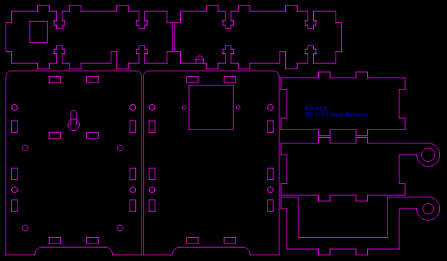
A few years ago I tried making some gears for a concentrated solar power heliostat. The design was quite primitive and I only had fleeting access to a cutter. I wanted to be able to generate DXF files parametrically, written in Python. I have previously used the SDXF library, but this time the dxfwrite library looked better.
The code has changed over time, but it now provides a powerful library for creating designs purely in Python.
I've put the libraries and all the designs on GitHub
The library allows you to construct designs using a few basic classes. Polygon (and Rectangle), Arc (and Circle) and Collection. You can rotate, translate, splice polygon sections into a design, add curved corners etc.
Boxes
My first design was a box in 3mm acrylic for an Arduino Nano, interfaced to a relay board. I've been using one recently to control a bread proofing box.
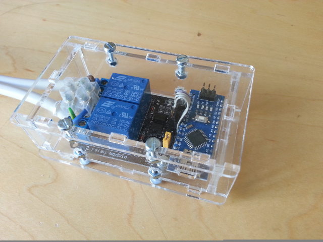
I was pleased with how this turned out, for my first attempt. It all fits together very snugly, using tabs to interlock the parts, and an M3 captive T-nut design. I also added stress relieving holes into the design to prevent cracking. I made no allowance for kerf. The cut-out for the mini-USB socket fitted perfectly.
The next design was a similar, a combined PIR and temperature sensor for the Olimex ESP8266 dev board.
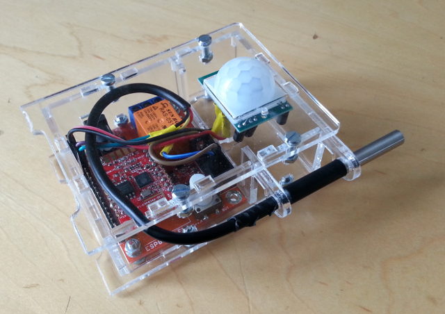
This took a couple of iterations to get right. The mounting holes for the DS18B20 temperature sensor were too small in this version.
Gears
Having got to grips with making simple boxes, I had a look at gears. I've always been fascinated by automata and clearly laser cutters are ideally suited to making some of the accurate complex shapes that are required.
As I mentioned above, I designed some gears a few years ago. But I didn't know anything about gears then. This time I did a bit of research and discovered that most gears are involute gears. This is a clever design that gives optimal smooth power transfer between the gears. They were designed by the brilliant mathematician Euler. I got side-tracked reading about him.
I looked at pages and pages of mathematics, but the explanation I liked the most is The Involute Curve, Drafting a Gear in CAD and Applications By Nick Carter. This drafting approach fitted well with my Python library, so I came up with a simple implementation :
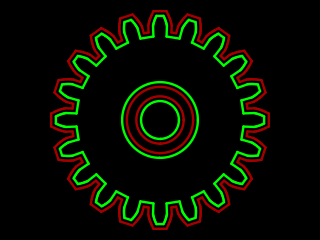
One problem with cutting accurate shapes is the kerf eats into the designed shape. For well fitting gears I needed to correct for the kerf. I came up with a relatively simple approach that calculates a line running parallel (by half the kerf width) to the shape to correct. This seems to work quite well.
The involute gear profile (green) and a kerf corrected cut (red), look like this :